From the radio to the assignment engine, one company owns the stack
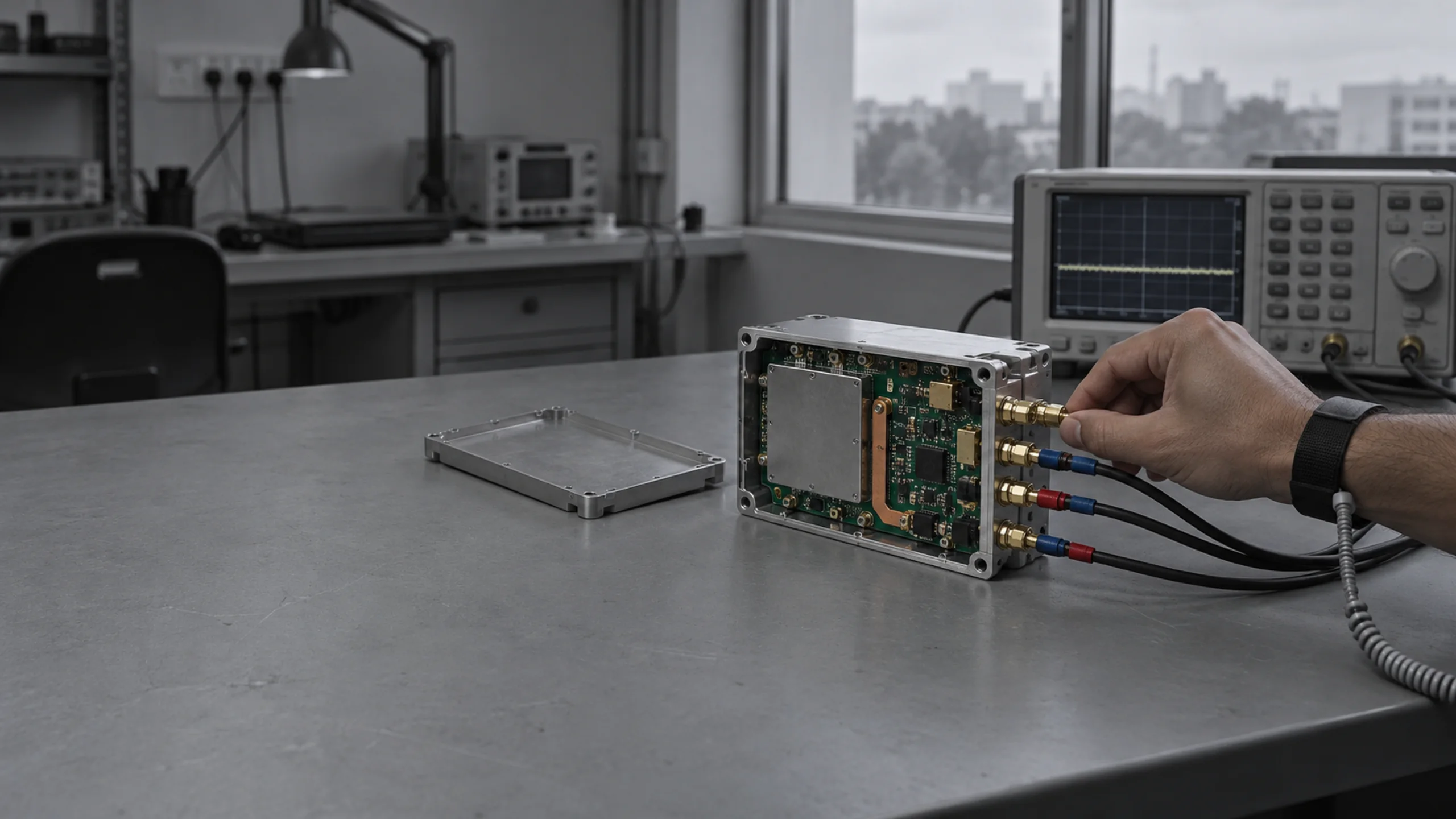
The RF communication module, the navigation stack, the perception stack and the command layer are built in house. We are not integrating a third-party autopilot with a third-party radio and calling the result a system.
Three layers, two directions of flow
Every section below is a zoom into one layer of this diagram. Interfaces between layers are named because the interfaces are where integration risk lives.
Command
The command layer takes a stated intent — jam this grid, hold eyes on this ridge, move this load — and resolves it into tasking for specific assets. It matches the capability the intent requires against what each asset is carrying, where it is, how much endurance it has left and whether it currently holds a link. The operator states what they want. The layer works out who can do it.
It proposes; it does not commit. Every assignment that results in an effect passes an authorisation gate held by the operator, and that gate is a property of the architecture rather than a setting.
The one step the system cannot take for itself
An assignment reaches the operator with the reasoning that produced it. Approving is a person’s action, it expires rather than persists, and it is written to the mission record.
Span of control nominal
Grid 43R FQ 8214 6390
Alt 620 m AGL
Bearing 041° · range 1 480 m
Speed 18 km/h · heading NE
First seen 14:31:08 · held 00:04:12
An asset drops out mid-task
Losing an asset is the normal case, not the exception. The question worth asking is what the remaining assets do about it without being told.
Four assets tasked. A-02 holds the track, A-03 holds the relay.
link lost→2.4 s
A-04 is retasked to the track and the relay repositions to close the gap. The operator is told what changed rather than asked to fix it.
Shown at block-diagram level. The allocation method itself is covered under NDA at briefing.
Network
One module carries three bearers: an RF mesh between agents, terrestrial 4G/5G where a network exists, and SATCOM beyond it. Each asset holds whichever bearers its class can carry, and the module selects between them on link quality rather than on a fixed priority the operator has to manage.
The mesh is the layer that matters, because it is the only one that keeps working with no infrastructure at all. Agents relay for each other, so an asset beyond the ground station’s own range stays reachable through the assets between them.
A bearer drops
Failover happens without operator action. What matters to an evaluator is which assets keep a link and which do not.
Assets holding mesh or cellular keep a link. The two SATCOM-dependent assets fall back to mesh at reduced range.
No asset depends on cellular alone. Cellular is a bearer of convenience, never the only path.
Every asset executes its last authorised task and returns. None continues acting on stale tasking.
Mesh range is line of sight. In broken terrain a ridge between two agents costs the hop, and range falls well below the open-ground figure — which is why a relay asset is positioned from terrain rather than flown in a fixed pattern. Cellular depends on a network that may be absent, congested or hostile. SATCOM adds latency and costs mass and power that a light airframe cannot spare.
We do not claim a jam-proof link. We claim that loss of any one bearer does not isolate an asset that holds another, that the mesh reforms without operator action, and that an asset which loses all bearers executes its last authorised task and returns rather than continuing to act on stale tasking.
Agent
An agent has to know where it is and what is around it without assuming a satellite fix. Three navigation techniques run on the asset, each suited to different conditions, and the estimator weights them on measured quality rather than on a fixed order. Position is always reported with its confidence, so a degraded fix is visible as degraded rather than presented as certain.
Perception runs onboard. Detection and tracking happen on the asset so that a link outage costs bandwidth, not the ability to see. What crosses the link is the resulting track, not the raw video.
The default in daylight over textured ground. Cheap in mass and power, and available on every tier.
Tier 3 and above. Works in darkness and holds geometry where vision has nothing to lock onto.
Bounds the drift of the other two by matching what is seen below against stored terrain.
Drift figures are measured over closed-loop runs on our own airframes and are stated as observed, not as specification. How the estimator weights the three is covered at briefing.
The fix is jammed or spoofed
Jamming denies the fix. Spoofing is worse: it supplies a false one that looks valid. Both are assumed.
The estimator drops GNSS and continues on VIO, LIO and terrain matching. Position confidence is reported honestly as it degrades rather than being held at a false certainty.
A GNSS solution that disagrees with the inertial and visual solution beyond a bound is rejected, not averaged in. Disagreement is surfaced to the operator as a condition of the area.
The ground station shows which navigation sources each asset is currently using and the confidence of its position. A degraded asset looks degraded on the screen.
Tiers are defined by sensor set, because that is what actually determines capability
A tier named after a behaviour is unfalsifiable. A tier named after its sensors tells you what it can and cannot do, and what it costs in mass and power.
Three things that sit across every layer
Assurance, validation and indigenisation are not features of one layer. They are properties of how the whole thing is built, and each is a named line in a procurement evaluation.
Assurance and security
Stated as posture, not as certification we do not hold.
AES-256 in transit across every bearer, with keys provisioned per mission and no static key shared across a fleet. The provisioning mechanism is covered at briefing.
Flight computers verify a signed image at boot and refuse to run an unsigned one. A recovered airframe cannot be reflashed into a working asset without our signing key.
Every board carries a recorded origin, and the build record ties a serial number to the components in it. We can state where each part of a delivered unit came from.
Nothing in the stack contacts us. There is no telemetry channel to a vendor server, no update that arrives unasked, and no dependency on our infrastructure for a mission to run.
We are building to the documentation and test standards Indian procurement applies, and we will say plainly which we hold and which we do not rather than implying coverage we have not earned.
Flight and drive control run against a simulated airframe. Control laws, failsafes and mode transitions are exercised before hardware exists.
Multiple agents, a terrain model and degraded links. Assignment, reassignment and mesh behaviour are exercised at fleet scale.
Real flight computer, real communication module, simulated world. Timing and compute limits show up here, not on a range.
What cannot be proven in software: aerodynamics, propulsion, RF propagation over real terrain, and the integration of all of it.
How we build
Indigenisation as an engineering decision, not a paperwork exercise.
Range across the platform classes. The figure moves with powerplant and link set — an Indian-made engine raises it, SATCOM lowers it — and the configurator computes it per configuration rather than quoting a single number.
Airframe structures, the communication module, flight and drive control, the navigation and perception stack, and the ground station. These are the parts where a dependency would be strategic rather than commercial.
The IC engine on the 20 kg class, machined and composite components, wiring and connectors, and assembly. Domestic supply where a domestic supplier exists at the quality required.
Compute modules, imaging sensors, certain RF front-end components and SATCOM terminals. Stated openly, from named non-Chinese sources, with a documented second source where one exists.
Component origin is verified at goods-in against supplier declarations and recorded per serial number, not accepted on a distributor's word. Indigenous content is computed from that record as a share of BOM value.
Everything below block level is a conversation
Architecture, interfaces and trial data are released under NDA. Bring your evaluation criteria and we will walk the stack against them.